The FPGA garage door simulator accurately models the operation of the garage door which your controller will control. You will demonstrate the operation of your controller using this simulator. When the simulator powers up, it goes to the initial state of the garage door which is full closed. The right two seven-segment displays show the current position of the garage door from full closed (position 0) to full open (position 10). When the simulator detects an error in the operation of the door, the left two displays show the detected error using the Error Condition Codes specified below.
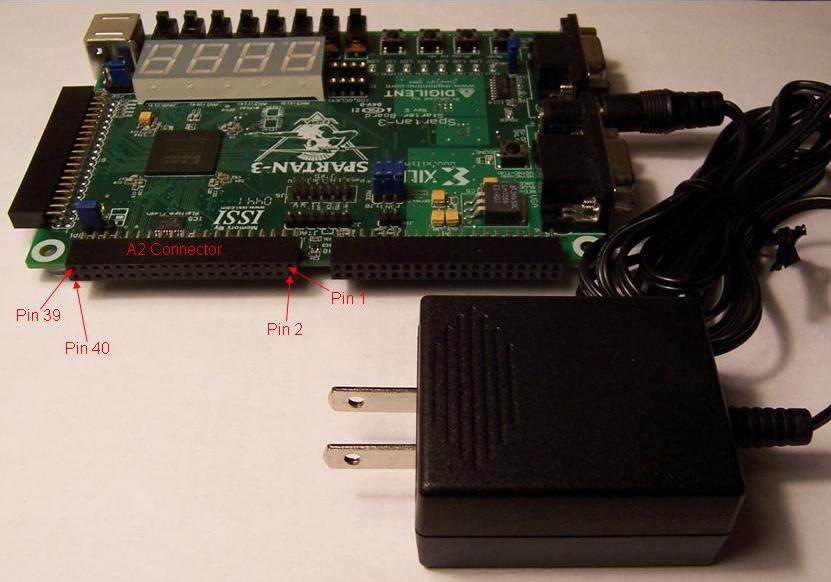
Your controller will connect to the simulator through digital I/O ports on the purplebox. These ports are on the 50-pin purplebox connector brought to the breakout board. The simulator input and output signals are on the Digilent Spartan 3 FPGA board's A2 connector. Use the photo and table below to locate this connector and the signal pins. Also, note the attachment of the power supply.
Connections to Simulator |
|||
| Signal | Direction | Pin | Notes |
| Digital ground | -- | A2-1 | Connect to digital ground on purplebox |
| Full open | Output | A2-5 | Garage door at full open position (position 10) |
| Full closed | Output | A2-7 | Garage door at full closed position (position 0) |
| IR beam broken | Output | A2-9 | Passthrough of Beam broken pushbutton when IR beam on input is on |
| Overcurrent | Output | A2-11 | Passthrough of Overcurrent pushbutton when motor is running. |
| Remote pushbutton | Output | A2-13 | Passthrough of remote pushbutton |
| Motor up | Input | A2-6 | Controller command to open garage door |
| Motor down | Input | A2-8 | Controller command to close garage door |
| IR beam on | Input | A2-10 | Controller command to turn IR safety beam on |
| Simulator reset | Input | A2-12 | Reset simulator (active low, minimum 50 nsec). You should reset the simulator when you start your controller program. |
The Direction column is with respect to the hardware simulator.
You can monitor many aspects of the garage door simulator operation by looking at the LED indicators. LEDs showing simulator inputs display either the input signals from the controller, or, if the simulator is in standalone mode, the standalone mode switch inputs.
LED Indications |
|
| LED 0 | Full open |
| LED 1 | Full closed |
| LED 2 | Motor up |
| LED 3 | Motor down |
| LED 4 | IR beam on |
| LED 5 | IR beam broken |
| LED 6 | Overcurrent output |
| LED 7 | Remote pushbutton |
The table below lists the assignment of functions to the four pushbuttons on the Spartan 3 FPGA board.
Pushbuttons |
|
| PB 0 | Reset simulator to initial state |
| PB 1 | Beam broken |
| PB 2 | Motor overcurrent |
| PB 3 | Remote pushbutton |
The simulator has a standalone mode of operation. When in standalone mode, you can experiment with the operation of the garage door using the Standalone Mode Switches shown below. You put the simulator in standalone mode by turning on the Standalone mode switch (SW 3). The simulator ignores inputs from the controller when in standalone mode, but continues to respond to the pushbuttons specified above
Standalone Mode Switches |
|
| SW 0 | Motor up |
| SW 1 | Motor down |
| SW 2 | IR beam on |
| SW 3 | Standalone mode |
The simulator detects several conditions which indicate incorrect operation of the controller. The left two seven-segment displays show the detected error using the Error Condition Codes shown below. After detecting an error, the simulator must be reset to its initial state by pressing the reset pushbutton.
Error Condition Codes |
|
E1 |
Controller did not stop motor when door was full open |
| E2 | Controller did not stop motor when door was full closed |
| E3 | Motor up command not active within 1 second after IR beam broken |
| E4 | Motor up command active more than 1 second after motor overcurrent |
| E5 | Motor up and motor down commands active at the same time |
| E6 | IR beam on when motor up command active |
| E7 | Motor up command not active within 1 second of motor overcurrent indication when motor down command active |
| E8 | IR beam off when motor down command active |
$Id: GarageDoorSimulator.html 173 2013-01-06 21:46:34Z jrv $